
This article outlines how FEV has optimized the H2 powertrain layout to resolve the trade-off between transient performance and near zero emission. The degree of hybridization, different turbocharger technologies and the mixture formation (external and internal) have been investigated using FEV’s dedicated H2 ICE simulation tool chain to identify tailored powertrain solutions.

1. Combustion systems
Current H2 engine development mainly uses a spark ignited “Otto” combustion principle. The air/fuel mixture is ignited by the energy source provided by a spark plug.
1.1. Port fuel injection system (PFI)
With PFI, hydrogen is injected into the intake manifold at low-pressure levels (~10 bar). The long time for mixture preparation ensures a high level of mixture homogeneity. The occurrence of rich air/fuel areas is limited, which reduces the NOx formation and the knock tendency. On the other hand, the external mixture formation reduces the cylinder filling. Hence, a PFI configuration represents an attractive solution for retrofitting lower power applications.
At FEV, a 7.7L engine has been modified for H2 PFI operation. The original single-stage turbo was replaced by a two-stage turbo to achieve high air/fuel ratios. Piston design was also optimized to ensure knock and pre-ignition-free operation [1]. Eventually, CNG and diesel like BMEP levels were reached with a maximum of 19.6bar. Also, achieving the CNG engine power level of 220 kW was possible.
With a PFI layout, safety risk must be mitigated because of backfire. There, valve timing adaptation is recommended. Nevertheless, load response remains a drawback. A mild hybrid support can improve the transient behavior. Choosing a DI system is another possible option.
2.2. Direct injection system (DI)
With DI, H2 is directly injected into the cylinder with a pressure ranging from 15 to 60 bar. The risk of backfire is significantly reduced. Moreover, the volumetric efficiency is not impacted, resulting in better engine efficiency and faster transient response.

The experimental investigations shown in Figure1 were carried out with a heavy-duty single cylinder engine. Comparing PFI and DI at the same boost pressure is more representative to real engine operation. Then, DI offers an advantage in NOx emissions at same engine efficiency level.
A major challenge for DI systems is to provide PFI-like mixture homogeneity. Further improvements are expected thanks to simulation results.
2. Simulation tools
2.1. Mixture formation optimization of DI system with 3D-CFD simulation
The mixture formation is key to enhance engine efficiency while keeping the NOx raw emissions low. Aiming for the best mixture homogeneity, the interactions between fuel injection and charge motion are deeply studied. To this end, FEV has developed a comprehensive simulation tool chain, tailored for H2. Engine data and optical chamber investigations are continuously being validated against simulation results, ensuring good level of accuracy.
In the given example, parameters such as injector location, spray forming cap and charge motion (tumble, swirl) have been studied. In Figure2, iso-surface of 1% H2 by mass fraction is represented. For the early configuration, the hydrogen is trapped near the cylinder liner due to the base swirl inside the cylinder. The tumble motion generated by the injection is not strong enough to bring hydrogen towards the centre of the cylinder. As indicated by the high standard deviation of lambda, poor homogeneity is observed. As part of the optimization, the swirl from the ports was reduced. The cap design was readjusted to produce more conventional tumble. The combination of these changes was sufficient to significantly improve the mixture homogeneity [2].

2.2. Transient performance evaluation of different turbocharger technologies with 1D simulation
Knowing that boost requirement is high in H2-ICE, 1D simulations are performed to evaluate how an e-turbo can improve the transient response.
Load steps at constant engine speed (1000rpm and 1500rpm) are investigated for three different cases (conv. VGT TC and two different e-TCs featuring respectively A kW and B kW of e-power). The base VGT is carried over from the Diesel engine variant. The simulation models have been matched with test bench data.
Low engine speeds are here simulated, for which getting sufficient low-end torque in short time is a challenge. As depicted in Figure3, lambda limitation (1.8 at 1000rpm and 2.1 at 1500rpm) is applied to avoid knock and NOx overshoot.

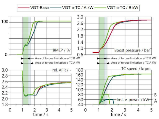
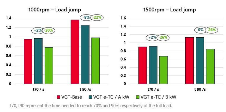
Figure 4 displays improved response time when using an e-turbo. With a A kW electrical support, the transient performance is close to the base turbocharger. An assistance, greater than A kW, would be more beneficial to counteract the added inertia of e-turbos. This is confirmed when looking at the B kW curve of the VGT e-TC, which offers better overall performance.
With the right e-support, e-TC turbo layout brings higher power rating and better transient performance.
3. Summary and outlook
H2-ICE technology offers a solution to realize carbon neutral transport.
PFI technology has limits in terms of operational safety, power density and transient response.
DI has great potential to address the backfire issue and improves the transient response.
For even higher power densities and better transient response, a combination of DI with an e-turbo is an attractive solution.
Associated with the right hardware, smart engine control can unlock even further performance potential. To this end, FEV has also developed engine control functions for H2 combustion control.
References
1. International Congress Engine Congress, Baden Baden 2021 – Combustion system development for hydrogen fueled heavy duty internal combustion engines. L.Virnich, B.Lindemann, M.Müther, A.Dhongde, M.Schönen, J.Geiger, A.Kremer
2. ATZ Heavy duty Worldwide, 04/2021 – Advanced Simulation Methodologies for Hydrogen Combustion Engines. A. Dhongde, H. Sankhla, L. Virnich, P. Recker
S. Ghetti, FEV Europe GmbH, Aachen, Germany
D. Van der Put, MBA, FEV Group GmbH, Aachen, Germany
L. Virnich, Dr.-Ing., FEV Europe GmbH, Aachen, Germany
S. Schaub, Dr.-Ing, FEV Europe GmbH, Aachen, Germany
Source: VDI


